2.Hardware Connection
Hardware List
Component |
Description |
|---|---|
ESP32S3 Module (×1) |
Core microcontroller with integrated Wi-Fi/Bluetooth functionality, responsible for voice recognition, AI dialogue processing, and system control |
400 Tie-Points Breadboard (×2) |
Solderless platform for quick electronic component connections |
LAFVIN AI Chatbot Shield (×1) |
Specialized expansion board that simplifies wiring, providing a plug-and-play solution for LAFVIN ESP32S3 AIChatBot functionality |
LAFVIN Audio Codec Module and Speaker (×1) |
High-quality audio codec for processing voice input capture and audio output synthesis |
2.0-inch TFT-SPI Display |
High-definition color display interface for real-time conversation content and system status information |
Jumper Wires |
Electrical connection wires between modules, ensuring proper signal and power transmission |
Buttons (x4) |
Physical interaction for text page navigation |
USB Data Cable |
Provides stable power input and data communication between computer and device |
Connection Instructions
If you are using the expansion board for wiring, the connection method between the ESP32S3 module and other components is as follows:
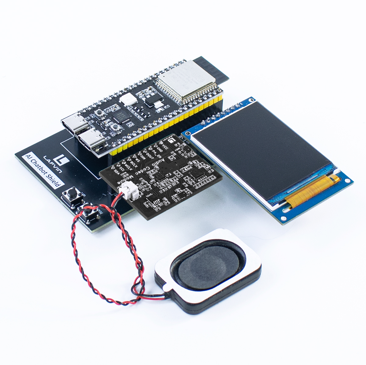
The completed connection with the expansion board should look like the image above
If you are using a breadboard for wiring, the connection method between the ESP32S3 module and other components is as follows:
LAFVIN Audio Codec Module Connection
VCC - 5V
GND - GND
PA_EN - GPIO48
DOUT - GPIO45
DIN - GPIO12
WS - GPIO13
BCLK - GPIO14
MCLK - GPIO38
SCL - GPIO2
SDA - GPIO1
2.0-inch TFT-SPI Screen Connection
GND - GND
VCC - 3V3
DC - 39
CS - 47
CLK - 41
SDA - 40
RES - RST
BLK - 42
Button Connection
Page Up - GPIO20
Page Down - GPIO19
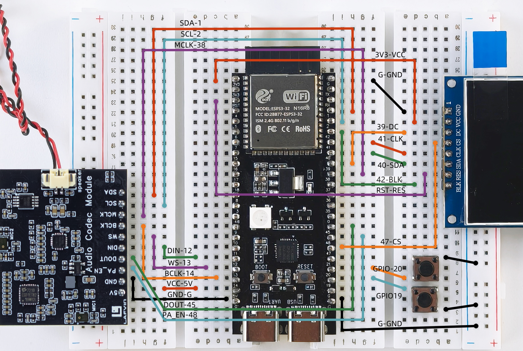
Warning
Be sure to connect the modules according to the connection diagram above, otherwise the modules may be damaged.
Assembly Steps
Insert the modules into the corresponding interfaces on the expansion board
Install the corresponding modules according to the description on the expansion board
If using a breadboard, check that all connections are secure and avoid false connections